This example shows a glass textile reinforced epoxy beam
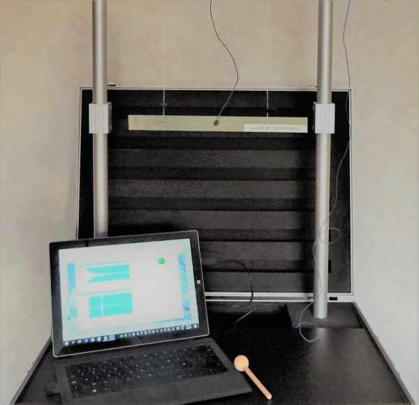
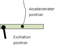
The test beam is freely suspended on 2 thin nylon threads. The suspension threads are preferably positioned at about one quarter of the length of the beam (in the nodal lines of the vibration mode) to reduce the influence of the threads as much as possible. Fix the accelerometer in the middle of the beam and excite the beam at a free end (or in the middle at the opposite side of the accelerometer).
In this configuration, the basic bending modal shape is easily excited, because this modal shape shows big vibration amplitudes at the free ends and in the middle of the beam (see moving modal shape below).
Basic Modal bending shape
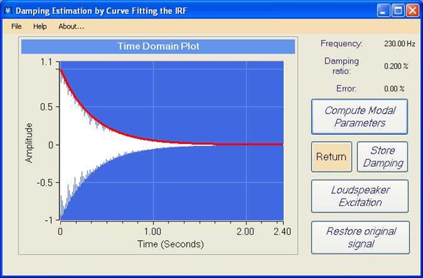
The measurement screen of the resonalyser shows a clear resonance peak (in the example below at 230 Hz)
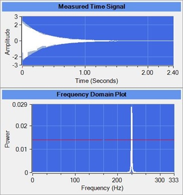
Time domain signal (above) and Frequency domain signal (under)
The mass of the used accelerometer can be taken into account. Therefore the user must indicate the resonalyser software the mass and position of the accelerometer (Mass = 0.0012 kg and the position is node number 5 in the example below).
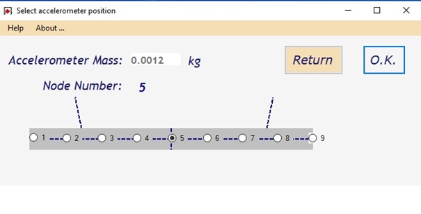
Position of the accelerometer (Resonalyser software screen)
By curve fitting the decaying signal, the damping ratio of the bending modeshape of the beam can be identified.
With the measured frequency, the resonalyser software can compute a good value for the Young’s modulus in the longitudinal direction of the beam. The damping ratio provide a good value for the tangents delta of the Young’ modulus.