3 Different types of Orthotropic reinforcements
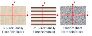
Most composite materials show orthotropic material behavior. This means that the elastic values have a mirror symmetry with respect to two perpendicular axes, the so-called “Material axes”. In the picture on the right these material axes are indicated as the (1, 2) axes and are parallel with the edges of the test plates.
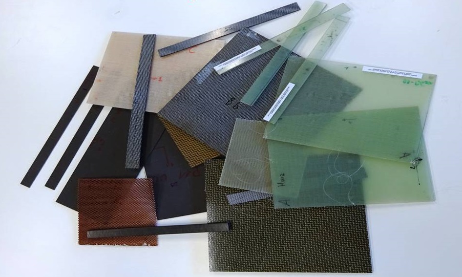
Composite materials include long fiber reinforced Thermoplastics, Metals and Thermo hardening materials. Composites can also be reinforced by small or medium small fibers. In this case the material behavior can be sometimes considered as isotropic. Typical reinforcement fibers are glass, Kevlar and carbon. Popular thermo hardening plastics are epoxies and polyesters. Popular thermoplastic materials for composites are Nylon, Polypropylene and many other recent plastics. Also metals like aluminum can be used as matrix material.
The stiffness behavior of orthotropic composite plates can be described by 4 Engineering Constants:
- The Young’s Modulus E1 in the 1-direction (Main orthotropic material axe)
- The Young’s Modulus E2 in the 2-direction (Perpendicular orthotropic material axe)
- Poisson’s ratio v12 (In plane coupling material property)
- Shear Modulus G12 (In plane shearing material property)
To make good test plates for composite materials, several layers of Unidirectional laminae or bi-directional textile reinforced layers can be assembled on top of each other. One must careful to orient all layers in the same direction (parallel to the plate edges) to maintain the orthotropic character of the test plate.
Composite material Beams and Plates
For Orthotropic composite test plates, the resonalyser procedure works as follows:
1. Measurement of the basic bending frequencies f1 and f2 of two beams cut along the sides of the test plate.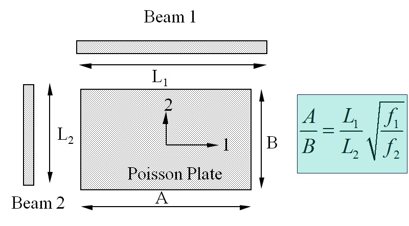
The basic bending frequencies of Beam 1 (f1) and Beam 2 (f2) together with the Beam Lengths L1 and L2 provide the correct aspect ratio A/B for a so-called “Poisson” Plate using the above formula.
Link to beam measurement
This allows cutting the test plate in the correct aspect ratio A/B for a “Poisson” plate. A Poisson plate is sensitive for all the Orthotropic engineering constants and can hence can identify all the engineering constants with the highest accuracy.
2. Measurement of the 3 first resonance frequencies of the Poisson plate
Link to plate measurement
The resonalyser procedure for Orthotropic composite materials is illustrated in the next example: example