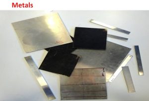
Metals considered as Isotropic Materials
Metals like aluminum and steel are one of the most used materials in structural engineering. For many practical engineering applications, metals can be considered as globally isotropic materials. The elastic behavior can hence be described by 3 engineering constants, a Young’s modulus E, Poisson’s ratio v and the shear modulus G. Because isotropic materials have only two independent elastic properties, there is a relation between the engineering constants:
G =E/2(1 + ν)
The Engineering constants E, G and v can be identified with 3 resonance frequencies measured on a square test sheet. Hence, no test beams are necessary.
Because many metal sheets are manufactured with hot or cold rolling, the material properties are oriented in the rolling direction and in the direction perpendicular on the rolling direction. Therefore they are not “perfectly” isotropic. Depending on the temperature and the thickness of the metal sheets the deviation of the global Engineering constants from Isotropic behavior can be neglected or can be rising up to 10%. The Resonalyser procedure on a square test sheet, considered as globally isotropic material, yield a global average over the area of the sheet. This is the value engineers can use in software packages for designing metal sheet parts. The Resonalyser automatically provides a result together with an uncertainty value. The more the metal test sheet deviates from perfect isotropic behavior, the larger the computed uncertainty bounds will be.
Example: Identification of an Isotropic Aluminum sheet
Metals considered as Orthotropic Materials
The resonalyser procedure can also identify the Engineering constants of metal sheets, considered (correctly) as Orthotropic material due to the rolling during manufacturing.
The stiffness behavior of orthotropic composite plates can be described by 4 Engineering Constants:
- The Young’s Modulus E1 in the 1-direction (Main orthotropic material axe)
- The Young’s Modulus E2 in the 2-direction (Perpendicular orthotropic material axe)
- Poisson’s ratio v12 (In plane coupling material property)
- Shear Modulus G12 (In plane shearing material property)
For orthotropic metal test plates, the resonalyser procedure works as follows:
1. Measurement of the basic bending frequencies f1 and f2 of two beams cut along the sides of the test plate.
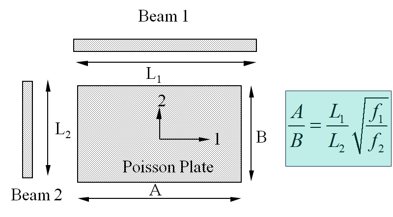
The basic bending frequencies of Beam 1 (f1) and Beam 2 (f2) together with the Beam Lengths L1 and L2 provide the correct aspect ratio A/B for a so-called “Poisson” Plate using the above formula
Example: Measurement on a test beam
This beam results allow cutting the test plate in the correct aspect ratio A/B for a “Poisson” plate. A Poisson plate is sensitive for all the orthotropic Engineering constants and can hence identify all the Engineering constants with the highest accuracy.
2. Measurement of the 3 first resonance frequencies of the Poisson plate
Plate measurement
The resonalyser procedure for orthotropic metal materials is illustrated in the next example:
Identification of an Orthotropic Aluminum Sheet
Metal bar testing
Tests on metal bars with the Resonalyser will provide the longitudinal Young’s modulus. The orientation of the bars can be random, in the rolling direction or perpendicular to the rolling direction. The longitudinal modulus can be higher or lower than the average modulus found on test sheets, considered as isotropic.
Example: Measurement on a test beam